555 Timer Ic Schematic Diagram / 555 Logic Diagram - Wiring Diagram Networks / The block diagram of a 555 timer is shown in the figure.. In this tutorial, 555 timer ic is introduced. It consists of two operational amplifiers operated in an open loop or comparator mode, rs latch with additional reset 556 is a dual timer ic. The 555 timer is a simple integrated circuit that can be used to make many different electronic circuits. Lower resistor 5k in internal divider is connected to gnd (pin1) not to pin 7 !!!! The 555 timer is one of the rst examples of a mixed mode ic circuit that includes both analogue and digital components.
1 internal diagram of 555 timer. Lm555 timer internal circuit block diagram. The 555 timer can provide time delays ranging from several minutes for one cycle of operation to many thousands of cycles per second. Learn about the 555 timer and how it works in astable mode. The 555 timer, designed by hans camenzind in 1971.
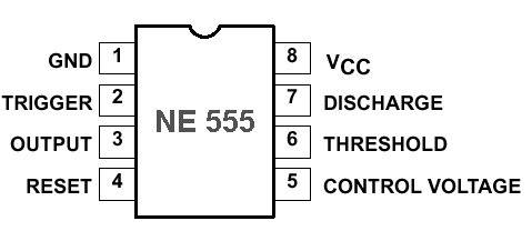
555 Timer IC Pin Diagram Features And Applications | 555 ... from circuitspedia.com 555 ic automatically switches back to stable state after some time, this time, for which the 555 stays in quasi stable state, is determined by the time constant of rc network in the circuit. This integrated circuit can be used in a variety of ways from which the basic one is to produce accurate. This tutorial provides sample circuits to set up a 555 timer in monostable, astable, and bistable modes as well as an in depth discussion of how the as indicated in the schematic in fig 5, connect a 0.01uf capacitor between pins 5 and 1. Ic 555 timer is a one of the most widely used ic in electronics and is used in various electronic circuits for its robust and stable properties. It includes all of the wiring diagrams and instructions you need to get started. If you still need a detailed understanding of the 555 timer. This article covers every basic aspect of 555 timer ic. Lm555 timer internal circuit block diagram.
Part a | drawing schematic diagram on fritzing beta for the schematic drawing, you may refer to my previous tutorial here for the keen details of drawing.
Print the diagram in the centre of a sheet of paper create a circuit using the ics pin locations. The 555 timer got its name from. Lm555 timer internal circuit block diagram. 1 internal diagram of 555 timer. The 555 timer, designed by hans camenzind in 1971.
555 Servo Tester - PMB-NZ - rcbeacon.com from rcbeacon.com Block diagram of 555 timer ic: The resistive network consists of three equal resistors (5k ohms each r). 555 ic automatically switches back to stable state after some time, this time, for which the 555 stays in quasi stable state, is determined by the time constant of rc network in the circuit. Derivatives provide two (556) or four (558) timing circuits in one package. Connect pin 6 to ground with a jumper wire (black). The 555 timer ic is a very cheap, popular and useful precision timing device which can act as either a simple timer to generate single pulses or long time. It consists of two operational amplifiers operated in an open loop or comparator mode, rs latch with additional reset 556 is a dual timer ic. In this article, we will cover about 555 timers.
Lm555 timer internal circuit block diagram.
555 ic automatically switches back to stable state after some time, this time, for which the 555 stays in quasi stable state, is determined by the time constant of rc network in the circuit. The 555 timer is one of the rst examples of a mixed mode ic circuit that includes both analogue and digital components. Part a | drawing schematic diagram on fritzing beta for the schematic drawing, you may refer to my previous tutorial here for the keen details of drawing. The primary purpose of the 555 timer is the generation of accurately timed single pulse or oscillatory pulse waveforms. You can watch the following video or read the written tutorial below. Block diagram of 555 timer ic: Learn about the 555 timer and how it works in astable mode. This circuit produces a two level of voltage for turn off and turn on. By ligo george 555 circuits, electronics, ic 555, ic, timer 0 comments. The 555 timer was introduced over 40 years ago. The 555 timer is an integrated circuit, it is extremely versatile and can be used to build lots of different circuits. Print the diagram in the centre of a sheet of paper create a circuit using the ics pin locations. In the schematic above, notice that the threshold pin and the.
The 555 timer ic is a very cheap, popular and useful precision timing device which can act as either a simple timer to generate single pulses or long time. Taking apart a circuit board or module and reconstructing its complete schematic is a valuable skill. In the schematic above, notice that the threshold pin and the. (1) for all available packages, see the orderable addendum at the end of the datasheet. Block diagram of 555 timer ic:
555 Timer Ic Datasheet Best Of | Wiring Diagram Image from mainetreasurechest.com Taking apart a circuit board or module and reconstructing its complete schematic is a valuable skill. The 555 timer datasheet specifies that 555 ic is a highly stable device for generating accurate time delays or oscillation. Block diagram of 555 timer ic: It consists of two operational amplifiers operated in an open loop or comparator mode, rs latch with additional reset 556 is a dual timer ic. It is basically a monolithic timer circuit which can be used in many applications such as this is the working principle of 555 timer ic. The resistive network consists of three equal resistors (5k ohms each r). The internal block diagram of 555 is as follows The 555 timer ic is a very cheap, popular and useful precision timing device which can act as either a simple timer to generate single pulses or long time.
In this article, we will cover about 555 timers.
This circuit produces a two level of voltage for turn off and turn on. Derivatives provide two (556) or four (558) timing circuits in one package. You can either follow the previous schematic or follow the breadboard wiring diagram below. The primary purpose of the 555 timer is the generation of accurately timed single pulse or oscillatory pulse waveforms. The 555 timer ic is an integrated circuit (chip) used in a variety of timer, delay, pulse generation, and oscillator applications. The 555 timer is an integrated circuit, it is extremely versatile and can be used to build lots of different circuits. 555 ic automatically switches back to stable state after some time, this time, for which the 555 stays in quasi stable state, is determined by the time constant of rc network in the circuit. Lm555 timer internal circuit block diagram. It consists of two operational amplifiers operated in an open loop or comparator mode, rs latch with additional reset 556 is a dual timer ic. The 555 timer ic is an integrated circuit (chip) used in a variety of timer, pulse generation, and oscillator applications. If you still need a detailed understanding of the 555 timer. Simple ne555 ic tester circuit diagram. Block diagram of 555 timer ic:
Capacitor c1 will need to be experimented for the 30 555 timer schematic. The 555 timer ic is a very cheap, popular and useful precision timing device which can act as either a simple timer to generate single pulses or long time.


0 Komentar